

Visual overlaps in BIM drawings can look like geometry errors even when the underlying building model is correct. Snaptrude explains that teams should first determine whether a problem comes from display order and visibility settings or from actual model geometry before moving, trimming, or deleting objects.
Display-order problems affect how lines, annotations, regions, images, and details appear within a particular representation. Geometry problems are different because physical model elements occupy incorrect locations, intersect improperly, or have incorrect dimensions. A masking region covering an edge or a hidden category making an object disappear does not necessarily indicate faulty geometry.
The article recommends starting with small, reversible tests. Teams should duplicate the affected view, identify the objects involved, isolate them, and inspect the same location in sections and 3D. A problem that changes with graphic overrides, annotations, or visibility settings is likely representational. If an intersection persists across views and affects measurements or quantities, the underlying geometry probably requires correction.
Teams should also examine category visibility, filters, element overrides, phases, design options, detail levels, transparency, linked files, and other view controls. Only one variable should be changed at a time so its effect can be verified. The correction should then be tested after saving and reopening the model and checked in required outputs such as PDFs.
Snaptrude also recommends establishing team standards that define which information must be modeled and which can remain view-specific. Reference files containing representative objects, details, annotations, imports, and overlapping graphics can help teams test behavior consistently.
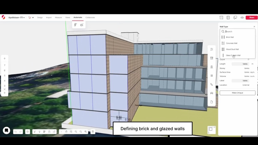
Snaptrude supports this diagnostic approach by connecting plans, sections, elevations, schedules, drawings, and 3D views. Collaboration, comments, version history, and branching can help teams review corrections without losing their context.
The central principle is simple: correct geometry only when the physical model is wrong. When the model is accurate, solve drawing problems through appropriate representation and display controls.
