
Ansys Powers Future Mobility Tech at CES 2025
Image: Ansys
Image: Ansys

PITTSBURGH, PA, Jan 6, 2025 – Ansys will showcase digital engineering solutions at CES 2025 to accelerate the next generation of safer and smarter vehicles. With recent advancements to its comprehensive product suite, Ansys directly addresses the industry’s most urgent challenges. By enabling faster innovation and improved productivity, Ansys simulation delivers significant time and cost reductions associated with physical prototyping.

Commitments to improved safety, demand for new features and functionality, and pressure to shorten design cycles despite increasingly complex engineering challenges have made traditional approaches to vehicle development ineffective. Ansys solutions help customers stay at the forefront of innovation by connecting and automating workflows, shortening design cycles, and reducing development costs through reliable design validation.

“Thanks to Ansys tools, we have realized a 25% reduction in product development cycle, 15% to 20% savings on engineering development costs, and the 15% to 20% improvement in product performance — to the satisfaction of our customers,” said Luciano Saracino, head of the Mechanics and Optics Center of Expertise, Marelli Electronic Systems.

Robust Optimization Accelerates Development

Automotive companies face challenges in design generation due to growing demands for shorter cycles and more intricate designs. Ansys solutions help address this, significantly speeding development — without compromising on accuracy — by increasing design exploration and optimization opportunities. Ansys’ open ecosystem also supports connected workflows that are primed for cloud computing, AI-enhancement, and digital twins. Booth features will include:

  • Ansys SimAI, a cloud-enabled generative AI platform that delivers easy, reliable performance prediction of physics behavior with lightning speed by leveraging NVIDIA GPUs. SimAI can be trained with existing simulation results for applications including fluid dynamics, thermal and electromagnetic performance, structural deformation, and more
  • The all-in-one Ansys ConceptEV design and simulation platform that accelerates EV powertrain system development and enables cross-functional teams to meet consumer and market requirements
  • Ansys Discovery 3D product simulation software and the NVIDIA Omniverse Blueprint for real-time computer-aided engineering digital twins for visualizing and accelerating large-scale computational fluid dynamics workflows

Connected, Software-Defined Vehicles Demand Simulation

Increasingly software-defined vehicles (SDV) rely on many systems, and systems of systems, working seamlessly together, creating valuable functionality for consumers and daunting complexity for engineers. Ansys solutions deliver robust virtual design and validation of new features, while offering safe, secure, and reliable performance without expensive hardware testing.

The Ansys booth will highlight these solutions with real-world examples and demonstrations, including:

  • Ansys Perceive EM radio frequency channel and radar signature simulation software integrated with an NVIDIA-accelerated shooting and bouncing ray solver for rapid computation of electromagnetics
  • A collaboration between Ansys, Cognata, and Microsoft enabling manufacturers and suppliers to work together on a web-based platform to test and validate sensor designs against certified sensor models

Solutions for Passive, Active, and Functional Safety

Ansys solutions improve vehicle safety through virtual prototyping and safety analysis. This includes crash safety to assure the well-being of the occupant if a crash occurs, active safety to help drivers avoid crashes, and functional safety to confirm software and hardware work as intended. Ansys technology can also help customers meet regulatory compliance through integrated workflows.

Examples of recent advancements and demonstrations of Ansys simulation for vehicle safety include:

  • A continued collaboration with Sony Semiconductor Solutions that significantly speeds time-to-compliance for ADAS/AVs through a more streamlined, high-fidelity perception sensor validation workflow for improved active safety
  • An advanced, integrated toolchain in collaboration with Kontrol, Microsoft, and TÜV SÜD to streamline safety, certification, and virtual homologation
  • Ansys digital twin technology for software and system virtual validation, featuring a video with Marelli Electronics Systems
  • Crash safety analysis using Ansys LS-DYNA structural simulation software and virtual human body models

“Every day, Ansys solutions are enabling customers to push the boundaries of comfort, safety, and performance of next-generation mobility,” said Walt Hearn, senior vice president of worldwide sales and customer excellence at Ansys. “By enhancing connectivity, ensuring safety, and accelerating development, Ansys enables automotive innovators to create safer, more efficient, and technologically advanced vehicles. With Ansys, companies can flexibly adapt to market demands and quickly address customer needs.”

Source: Ansys

Berms in Airports: Accidents Waiting to Happen

Killer berm. The berm with localizer array at Muan International in 2015. Image: Google Street View.

On December 29, 2024, a Boeing 737-800 flown by Jeju Air did a belly landing at Korea’s Muan International Airport. The aircraft overshot the runway and crashed into a massive berm that was constructed to elevate antennae for an ILS, an instrument landing system. The impact and the immediate fireball resulted in the death of 179 people. Two flight attendants strapped into the tail survived – barely. The crash was the worst airline disaster of 2024. It was not the first crash involving an aircraft hitting a berm, but it was the worst.

What Is an ILS?

How ILS information can appear in the cockpit. ILS. Image: Boldmethod

An ILS, or instrument landing system, includes an array of antennae about 10 ft tall. Every major international, regional and military airport uses an ILS. An ILS points a beam toward incoming aircraft so pilots can see their position relative to an optimum landing path. Their lateral position is determined by a localizer and their vertical position by a glidescope. An ILS is particularly useful in low visibility conditions.

Location of the Berm

A localizer at ground level at runway 06L of the Montréal–Trudeau International Airport, Canada. Image from Wikipedia by abdallahh from Montréal, Canada

In order to detect incoming aircraft from miles away and guide them in their approach, localizer arrays must be centered horizontally on the extension of the centerline of the runway. Because aircraft can sometimes overshoot the highway, their position is dictated to be outside the runway end safety area or RESA. The base for the array is usually on the ground, on the same horizontal plane as the runway. However, if the ground at the array’s horizontal location is lower than the runway, siting criteria for ILS, such as FAA Order 6570.16E, suggest a “pedestal” to raise the array. The FAA, as well as aviation agencies of other countries, specify the array and pedestal to be “frangible” structures, meaning they will break away or be crushed easily in a collision with errant aircraft.

The South end of the runway is 5.1m lower than the North end so the localizer array had to be raised. Image by mins on Aviation Stack Exchange.

Sorting through the wreckage. Note the gap in the berm after the 737 plowed through it. Image: YouTube.

Nowadays, airports in the U.S. and Canada all use frangible structures of low mass for elevated arrays, as opposed to berms, with a few exceptions.[i]. Berms, such as the berm elevating the localizer array at Muan International, is anything but frangible and low mass. It is 2.2m tall with a 0.6m thick concrete base, judging from the picture above. The aircraft appears to have pushed through the berm – but left it in pieces, suggests considerable mass.

In fact, the mass of the earth displaced in the berm in the Juan Air crash is on the same order of magnitude as the maximum takeoff weight (MTOW) of a Boeing 737-800, as shown below.[ii].

The MTOW (maximum takeoff weight) of a 737-800 is 79,000 kg, in the same order of magnitude as the 62,000 kg cylinder of earth it has punched out of the berm. The numbers get closer if you consider that the MTOW of a 737-800 includes 11,800 kg of fuel, and the doomed aircraft would have little fuel left when it was landing.

Off Course

Jeju Air was flying from Bangkok to the South of Muan. The aircraft first approached Maun International from the South and was to have landed using runway 01, as most aircraft that land there do. Muan International has only one runway but flights landing or taking off in the North direction use the runway 01 designation. But after a bird strike, the pilot issued a Mayday distress call and radioed a “go around,” meaning flying a full circle and trying another landing attempt in the original direction (North). Instead, for reasons that remain unclear at the time of this writing, the aircraft makes an abrupt 180-degree turn for a landing on runway 19, the same runway but going in the South direction.

Had the aircraft landed in the original North direction, it could still have overshot the runway and run into a localizer array. Unlike the localizer array off the South end of the runway, the localizer array off the North end appears to be at ground level (or very close to it), judging by Google Earth images. No berm is visible. If the array had frangible mounts, an aircraft flying over it would have just mowed down the array. Observers have speculated that if that had been the case, most, if not all, of those on board would have survived.

Those specifying or certifying the berm likely thought it impossible for an aircraft to reach it. After all, the berm was located a supposed safe distance from the end of the runway. The UN’s International Civil Aviation Organization (ICAO), which South Korea has adopted for its international airports, only requires 90m for a runway end safety area or RESA. However, an ICAO working paper suggests a 240m RESA for runways the length of Muan’s airport. Muan’s airport provided 260m of RESA – more than enough by ICAO guidelines.

In Harm’s Way

But berms have caused incidents elsewhere.

Minimum airport pitch attitude at point of impact with berm and photographs taken after the tail of a Boeing 747 broke off after hitting a berm during takeoff at Halifax airport on October 14, 2004. Image: Accident report by the Transportation Safety Board of Canada

On October 14, 2004, a cargo-carrying  Boeing 747 flown by MK Airlines failed to gain altitude upon takeoff at Halifax, Canada. Its landing gear struck the 10 ft high localizer array and its tail struck the berm and concrete base on which the localizer array was mounted, according to the official accident report published by the Transportation Safety Board of Canada. The tail broke off. The aircraft stayed airborne another 1,200 feet before it crashed and burned, killing all seven on board.

The berm was situated berm 1,825 ft (556 m) from the end of the runway. Similar to the runway at Muan, the Halifax runway tilted down, so the localizer array was raised with a berm.

On November 30, 2004, Lion Air Flight 538 hydroplaned while landing at Adi Sumarmo International Airport, Surakarta, Indonesia, striking a berm topped off with a concrete slab with a localizer array. Twenty-five of the 163 people on board died. Almost all of the structural damage of the aircraft and most of the fatalities and injuries were stated to be caused by the concrete slab.

Simply removing berms and replacing them with steel structures of less mass can still be disastrous. On June 1, 1999, a Douglas MD-82 flown by American Airlines landed during a storm at Little Rock National Airport. Upon landing in Little Rock, it overshot the runway and struck a localizer array but because the array was mounted on a frangible structure, there was almost no damage to the aircraft. Most of the damage was caused by a landing approach lighting system mounted on a nonfrangible structure. Parts of the structure crushed the nose of the aircraft and tore through the fuselage. Nine people were killed right away, and two more died from injuries. The FAA stated that a structure mounted in a flood plain could not be frangible because of the possibility of moving water, ice, and floating debris, but neither judge nor jury was sympathetic, and the airport was held liable for having dangerous (infrangible) support in a runway safety area.

A Berm-Free Future?

The Muan International berm is estimated to be between 3 and 4 m high and about 15 m thick at the base. Image from On PPEuNe, a pilot forum.

From the illustration alone (above), one might think that a design of berms would have an aircraft forced to do a belly landing slide up the embankment rather than crash through it. That may actually have happened in the Lion Air accident mentioned above, but in the recent far more deadly Jeju Air crash, the aircraft crashed through the berm with such energy that hardly a fragment remains identifiable. One solution is to create a berm with a broader base and, therefore, a smaller angle of incline that allows aircraft to slide up and over them, as the Lion Air flight has done. But why not get rid of berms that have any chance of impeding a takeoff or landing altogether, no matter how small the chance?


[i] In the research for this article, I confirmed localizer berms at Toronto Pearson International Airport and found mention of berms at two other Canadian airports.

[ii] The mass of a cylinder of earth with a diameter equal to 737-800 and a length equal to the thickness around the middle of the berm.

Ansys AVxcelerate Sensors Available on Cognata’s ADPH

Vehicle cuts in and automatic emergency braking brakes.

PITTSBURGH, PA, Jan3, 2025 – Ansys has announced AVxcelerate Sensors is accessible through Cognata’s Automated Driving Perception Hub. The ADPH platform runs on Microsoft Azure and 4th Generation AMD EPYC processors and Radeon PRO GPUs. ADPH gives original equipment manufacturers (OEMs) easy access to certified, web-based sensor models from manufacturers, enabling collaborative testing and validation of advanced driver assistance systems (ADAS) and autonomous vehicle (AV) functions using a high-fidelity simulation platform with virtual twin technology.

The ADPH allows OEMs and sensor manufacturers to test and validate certified sensors against diverse industry standards, including those put forth by the National Highway Traffic Safety Administration (NHTSA) and the New Car Assessment Program (NCAP). The platform currently includes Cognata sensor models for thermal cameras, LiDAR, RGB cameras with varying lens distortions, and leverages Deep Neural Network (DNN) technology that enables photorealistic images and simulations.

With the addition of Ansys AVxcelerate Sensors, users have access to physics-based radar models that reproduce EM wave propagation — accounting for material properties within high frequencies — to enhance signal strength and accuracy. The radar simulation provides raw data that can be used to test and improve the algorithms that process radar signal interference, like small changes in frequency caused by moving objects (doppler effect). When connected to a virtual model from a radar supplier, AVxcelerate Sensors produces a virtual twin of the sensor, enabling OEMs to evaluate its performance with enhanced predictive accuracy.

“We are excited to integrate Ansys’ radar simulation technology into the ADPH platform, bringing OEMs and tier-one suppliers an unmatched level of accuracy in sensor validation,” said Danny Atsmon, founder and CEO at Cognata. “Ansys’ ability to simulate complex EM wave interactions enhances our platform’s ability to deliver precise, real-world insights for radar-based ADAS and AV systems. This collaboration significantly advances the industry’s ability to test and refine sensor performance under diverse conditions.”

Cognata’s generative AI transfer technology, enabled by AMD Radeon PRO V710 GPUs, enhances the RGB camera simulation platform by delivering high-fidelity virtual sensors. It accurately captures and replicates the real-world behavior of sensors within the simulation.

“Ansys’ AVxcelerate Sensors platform includes real-time radar capabilities for accurate modeling of radar interactions in complex environments,” said Shane Emswiler, vice president of products at Ansys. “By offering the solution on Cognata’s ADPH platform, we are enabling customers to design for real-world operations to meet strict regulatory standards. As the industry works toward fully autonomous driving, safety validation is paramount, and the joint effort between Ansys and Cognata streamlines this typically long and complicated process.”

“We’re pleased to collaborate with Ansys and Cognata to enhance automated driving validation and simulation on Microsoft Azure,” said Nidhi Chappell, vice president, Azure AI Infrastructure at Microsoft. “By integrating Ansys’ advanced radar simulation technology, we’re empowering OEMs and tier-one suppliers with high levels of accuracy in sensor validation. This collaboration underscores our commitment to providing leading-edge cloud infrastructure that supports the development and validation of ADAS and autonomous vehicle technologies.”

Source: Ansys

IronCAD 2025 Released

Image: Ironcad

ATLANTA, GA, Jan 3, 2025 – IronCAD has announced the release of IronCAD 2025. This latest update introduces new features for design productivity and collaboration across platforms related to  industrial equipment, machinery manufacturing and metal fabrication industries.

The 2025 version of IronCAD added functionality includes:

  • Quick Access Favorites Catalog: Access frequently used design elements quickly.
  • Advanced Centerline Loft: New feature enables users to sweep two profiles along a path.
  • AI-Powered Assistance: The debut of the IronCAD AI Chatbot provides support tool for new users, and should be good for onboarding and troubleshooting.
  • Sheet Metal Design Enhancements: Quick Bend command allow users to apply multiple bends simultaneously.
  • Enhanced 2D Detailing: Improved AutoCAD block support and automatic dimension placement. make technical drawings faster and more efficient.

There’s More

IronCAD 2025 introduces features that aim to address common challenges in traditional CAD systems, such as cumbersome file management, limited flexibility and complex assembly workflows. The update reinforces IronCAD’s commitment to:

  • Simplifying complex designs through its Single Scene Unified Design Environment.
  • Enhancing team collaboration with Dual Kernel Support for seamless file compatibility.
  • Supporting manufacturers with tools tailored to bespoke machinery and modular product designs.

“IronCAD 2025 is a testament to our dedication to solving real-world challenges faced by design engineers,” said Cary O’Connor, senior VP of product and strategy at IronCAD. “This release empowers users to work faster, smarter, and with greater precision than ever before.”

IronCAD 2025 is available for purchase and trial. For more information or to download a 30-day trial, visit www.ironcad.com.

Source: IronCAD

Nemetschek Introduce AI and Sustainability Advancements at BAU 2025

Image: Nemetschek Group

MUNICH, GERMANY, Jan 3, 2025 – The Nemetschek Group, is presenting its latest software solutions and technologies at BAU 2025 in Munich. From Jan 13 to 17, 2025, the Group will be presenting new technologies for the digital transformation of the construction industry at a joint stand (Hall C3, Stand 322). The focus will be on artificial intelligence (AI) and sustainability.

The Nemetschek Group will use BAU 2025 to show how advanced technologies are transforming the entire building life cycle – from design and construction to the management and use of buildings. The joint stand offers visitors the opportunity to experience the Group’s software solutions live. Presentations, live demos and discussion panels will highlight the role of AI and cloud technologies in improving efficiency and resource management.

Innovation at BAU 2025: A strong presence with leading brands

At the Nemetschek Group stand, the brands Allplan, Bluebeam, Crem Solutions, dRofus, Graphisoft, Nevaris, Solibri and Vectorworks will be presenting their latest software solutions. With the dTwin platform, the Nemetschek Group shows how digital twins can contribute to an efficient and sustainable construction.

By focusing on open, compatible and scalable technologies, they demonstrate how the construction industry can position itself for the future through improved collaboration, optimized workflows and innovative approaches. In addition to numerous demos, start-ups in which the Nemetschek Group acts as an investor will also present their innovations.

“BAU 2025 is our canvas to paint a bold vision of the future – a future where sustainability and digital connectivity are the cornerstones of the construction industry,” says Yves Padrines, CEO of the Nemetschek Group. “Our groundbreaking artificial intelligence solutions are not just addressing challenges; they are redefining possibilities. From tackling climate change to optimizing resource use and alleviating the skilled labor shortage, we are pioneering a revolution. At Nemetschek, we don’t just create products; we craft comprehensive workflows that reimagine the entire ecosystem of construction and real estate. We are helping the industry constructing a smarter, more sustainable world for generations to come.”

BAU, held every two years in Munich, is one of the largest AEC trade shows in the world, attracting 250,000 attendees and over 2,200 exhibitors. It compares to Batimat in Paris with perhaps a few more attendees and a few less exhibitors. Both dwarf the biggest AEC tradeshow in the U.S., IBS in Las Vegas, with 70,000 exhibitors and 1,300 exhibitors.

Source: Nemetschek Group

PxE Next-Gen 3D Camera to Debut at CES 2025


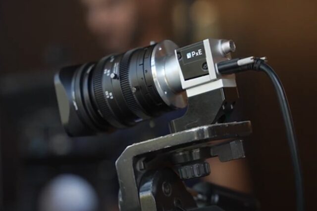
REHOVOT, ISRAEL, Jan 1, 2025 – PxE Holographic Imaging has announced it will debut its Holographic RGB-IR-Depth Camera at CES 2025. PxE’s technology enables 3D imaging on standard 2D digital cameras — from smartphones, laptops, cars and other camera-based systems — and turns them into 3D cameras that seamlessly merge the physical and digital world. A CES 2025 Innovation Awards honoree, PxE Holographic Imaging, will showcase its Holographic RGB-IR-Depth Camera technology in Las Vegas from Jan 5 – 10, 2025.

Whether using film photography or digital cameras, the fundamental physics of photography has remained virtually unchanged since its advent in the 1880s. Scientists and engineers have tried to achieve holographic imaging with digital cameras for decades. Still, no one has realized it to date, without degrading image quality or relying on cost-prohibitive technology such as lasers — until now. PxE’s Holographic RGB-IR-Depth Camera ushers in one of the most meaningful transformations in imaging since the invention of film photography- enabling 2D color, infrared and depth images per frame and on a single sensor. PxE’s technology not only has the potential to replace all existing 2D cameras on the market; it can also revolutionize how consumers and machines experience and capture the world through their everyday devices.

“Our RGB-IR-Depth Camera reduces the size and number of sensors needed along with the cost and complexity associated with today’s perception solutions,” added PxE Holographic Imaging CEO and co-founder Yoav Berlatzky. “We imagine a world where our 3D camera technology is ubiquitous: embedded in all cars with autonomous driving and obstacle avoidance features, used by consumers as facial ID to unlock their smartphone or laptop, to make payments via banking or shopping apps, or used for robotic navigation through advanced machine vision systems.”

How PxE’s Holographic RGB-IR-Depth Camera Works

PxE’s 3D imaging technology leverages the wave-like nature of light to simultaneously capture color, infrared and depth while improving the light sensitivity of cameras by 4x. The technology captures a light’s wavefront — its wavelength and curvature — to generate a “white light hologram” and then simultaneously decodes the hologram to output color, infrared and depth images without degrading image resolution. The result is an incredibly clear, radically upgraded three-dimensional image alongside a high-quality 2D color image and infrared image, all from a single frame and sensor. Utilizing its hardware and software, PxE upgrades standard 2D cameras into a multi-functional 3D system while maintaining the size, cost structure and image quality of standard cameras.

The PxE Holographic RGB-IR-Depth camera is not only multi-functional, it also addresses limitations of perception solutions that have been unsolved until now. For example, 2D cameras have inherent limitations on low-light performance. The Holographic RGB-IR-Depth camera dramatically improves upon the status quo, offering enhanced performance of cameras in the dark. It enhances the light sensitivity of cameras by transmitting 100 percent of the available light to the sensor (compared to 25 percent in 2D cameras), providing much better low-light performance than today’s cameras. Additionally, it can provide natively-fused color and depth images, mitigating synchronization issues and enabling a single line-of-sight.

“Today’s ever-connected, AI-driven world demands more and more from the underlying perception-based hardware systems they utilize, which are essentially the ‘eyes’ of the system — whether they’re used to drive our cars or keep people safe on factory floors. By enabling high-resolution images and accurate depth maps from a single sensor, PxE facilitates a safer world and is available for all machine vision systems and applications and at all price points,” said Yanir Hainick, chief technology officer, PxE Holographic Imaging.

PxE’s RGB-IR-Depth Camera technology will be sold to OEMs for use inside their devices –  smartphones, laptops, cars, drones, robots, security, and precision imaging equipment.


Source: PxE

Trimble Selects Best SketchUp Apps


WESTMINSTER, CO, Jan 1, 2025 – Trimble has announced the winners of the SketchUp0-60 Challenge, an initiative created by Trimble SketchUp and Trimble Ventures  aimed at encouraging innovative solutions for architects, designers, and project managers. The 0-60 Challenge invited entrepreneurs, early-stage startups and developers to leverage SketchUp to develop transformative technology solutions that solve common industry challenges.

Nine finalists selected from over 100 applicants were given an opportunity to collaborate with subject matter experts, innovators and technologists from within the Trimble network to transform their ideas into reality. After a three-month development process, the finalists demoed their solutions for a live audience at 3D Basecamp at Dimensions, Trimble’s annual user conference.

“The ideas and solutions that came to light through the SketchUp 0-60 Challenge are nothing short of transformative,” said Christopher Cronin, VP & GM, architecture, design and education at Trimble SketchUp. “We created the challenge to stimulate creative problem solving, encourage collaboration and connection, and help turn ideas into solutions that will have a real-world impact on AEC workflows. Together with a talented third-party developer community, we are pushing the boundaries of what’s possible and seeing how the integration of AI unlocks new levels of efficiency, interoperability and creative exploration for the SketchUp community.”

The SketchUp 0-60 Challenge Winners are:

First Place: ScaffPlan developed an extension that helps temporary works companies—builders of temporary structures used to support construction projects—create detailed drawings and documentation for scaffolding, formwork, propping, and shoring projects in SketchUp. The tool is designed to improve material utilization, assist with delivery scheduling, support on-site installation, and aid compliance with legal requirements and safety protocols.

Second Place: To streamline the design to construction documentation workflow between SketchUp and Revit, Skema’s new integration addresses the need for greater interoperability between both solutions. The integration provides designers, developers, builders and owners a seamless way to leveraging SketchUp for faster Building Information Models (BIM) development, reducing data loss and unnecessary remodeling, leading to increased efficiency and confidence.

Third Place: A plug-in from Spacely AI accelerates the process of creating high-quality renders of interiors by auto-populating 3D spaces with the appropriate entourage. The solution accelerates the time-consuming process of populating and rendering stylized 3D spaces, allowing interior designers to win more business, reduce costs and explore creativity.

Amazon Web Services “Scaled Thought” Award: Extracting precise data from designs and manually labeling components is tedious and error-prone, often leading to incomplete or inaccurate data. Scene Intelligence, a SketchUp plugin created by Loci, uses state-of-the-art AI models to classify components in SketchUp to IFC 4 standard at the click of a button. Scene Intelligence makes it easy to filter and view critical elements such as furniture and structural components. It also assists in generating a bill of materials efficiently.

Judges selected the winners based on three product categories and against six different criteria to measure the efficacy of the proposals. First, second and third place winners received cash prizes and Loci will receive technical expertise in three complimentary workshops led by Solution Architects at Amazon Web Services. All features are available to download and try on the SketchUp Extension Warehouse.

Source: Trimble

Korean Airliner Survives Belly Landing but Hits a Berm. 179 Dead.

Muan may be the worst place in South Korea for an airport. The south of South Korea, with its many islands, is a haven for seabirds. It has the highest incidence of bird strikes in South Korea. So, it was perhaps no big surprise to the pilot of Jeju Air flight 2216, a veteran with over 6800 flight hours, to be warned of bird strikes at 8:57 AM local time on a sunny Sunday, December 29, 2024 by Muan International’s air traffic control.

Fair warning, indeed. With the air thick with birds, one or more may have been ingested by one of the engines on the Boeing 737-800. The pilot issued a mayday alert. A local news video captured flames briefly erupting from an engine. The pilot attempts to land, but the landing gear is not descending, and he is forced to go around and try again. A few minutes later, still without landing gear down, the pilot does a belly landing. The speed is visually estimated to be “about 200 miles per hour,” higher than the 120 to 150 mph normal for a 737-800. The aircraft makes contact with the ground less than halfway down the 2,800 m (9,186 ft) runway, giving it precious little distance to slow down. A 737-800 requires a minimum of 1,830 m to stop with landing gear and brakes. Coming in hot, sliding on its belly with no brakes, no thrust reversers and with flaps level, the aircraft overshoots the runway, covers 140 meters of open ground and slams into an earth and concrete structure. It explodes in a ball of flame. Of the 175 passengers and 6 crew, only two flight attendants buckled into their jump seats at the back of the aircraft and survived, though both were seriously injured.

Muan International Airport is a regional airport 170 miles south of Incheon International airport in Seoul, South Korea.

The investigation has begun. We won’t know what caused the landing gear not to be deployed and if and how the landing gear failure and the bird strike were related. It will be months before an official report is available.

However, to David Learmont, a former RAF pilot and aviation journalist interviewed by Sky News, the cause is clear. He puts the blame completely on the berm, a concrete/earthen structure off the end of the runway, calling its placement “criminal.”

The berm holds the localizer for the ILS (instrument landing system), part of the aircraft sensing system that airports use, but instead of being so massive, it should have been in a more forgiving structure, says Learmont.

The pilot had been heroic, says Learmont. He executed a perfect landing under the most demanding of situations. He reviews Google Maps and visually estimates enough “level ground” after the runway to have slowed the aircraft a great deal, if not stopped it altogether, and “more people would have survived.”

The localizer, vital for bad weather and low visibility landings, are typically installed at ground level or on a “collapsible” structure, says Learmont.

From the aerial view, it may appear that the berm serves as protection for the traffic on the road encircling the airport and the highway further down, but its true purpose is to elevate the localizer.

The berm at Muan International Airport

The Candy Cane Drops and Shatters

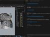
‘Tis the season for festive engineering. This year, I decided to put my finite element analysis skills to work on a seasonal icon: the candy cane. We all know the perils that follow once you see your beloved candy cane fall and shatter. With Ansys LS-Dyna, I set out to simulate what happens when a candy cane falls onto a rigid surface. Read on to see how I designed the experiment, developed a material model, and simulated the drop test—all while keeping things festive!
Building the Model

To capture the candy cane’s iconic stripes in the model, I utilized mesh morphing. Although the candy cane’s twisting introduced some skewing in the elements, we embraced the festive spirit and made the engineering assumption that this was acceptable. Hopefully, this keeps us off Santa’s naughty list!

I started this project with a candy cane plan, A sweet little profile to fit in my hand.

A cylinder came next, with a mesh oh so fine, to twist into something quite festive, divine.

Some profiles I made to help with the task, for morphing the mesh—it’s easy, just ask!

The stripes now appear in a classic design, they twist and they shimmer, a sight so fine.

With morphing complete, the mesh is just right; this candy cane’s ready—it’s quite the delight!

Material Definition

To understand the candy cane’s brittle behavior, I performed a simple 3-point bend test on a sample. The Sample broke around 50N of pressure. I did a quick bend test simulation in LS-Dyna to help determine Young’s modulus and fracture stress to use in the drop simulation.

There are many material models available in LS-Dyna, and a quick search of material databases yielded no results for candy canes. So, to keep things simple, I used *MAT_ELASTIC and *MAT_ADD_EROSION to add a sudden failure criterion since candy canes shouldn’t have much, if any, permanent deformation before failure. A more sophisticated material model could be built, but in the interest of having more time for family this holiday season, we will keep it simple.

Candy Cane Bend Test 1

Candy Cane Bend Test 2

After the simulation we can output a force vs displacement curve to help validate our material model. You can see below my generated graph. Our simulation showed the break around 47N of force, which closely matches physical testing.

Drop Test Simulation

With the material model defined, I simulated the candy cane falling from a height of approximately 6 inches onto a rigid surface. To speed up the simulation time, I set an initial velocity of the candy cane just before impact. Key highlights of the drop test include:

Fracture Animation: The simulation showed the candy cane shattering into pieces, mimicking real-world behavior.

Visualization of the stresses during the impact event.

Once the model is built and running, it’s easy to test additional load cases for different drop positions. For curiosity’s sake, I decided to see what would happen if it were dropped on the end instead of the side. The results are below.

Results and Insights

The drop test showed just how brittle candy canes are. While I’ve always known they were fragile, I was surprised to see it break into so many pieces from such a low height. It might be interesting to revisit this simulation with the plastic wrapping included to evaluate its effect on the results. Simulating the shipping packaging could also add an additional layer of complexity, but for now, let’s enjoy the festive chaos of our shattered candy cane this holiday season.

 

Scanners Make Billion Point Models. What’s Wrong with That?

Trimble’s X9 laser scanner is one of the best laser scanners in the industry. Set it up on a tripod, push the button on Trimble’s purpose-built tablet, and the scanner comes to life and starts whirring and spinning. In 2 and a half minutes or less, at a rate of over 2 million points per second, it has recorded the entire scene within 2.2 mm accuracy (at 20 meters).

I am hearing of the X9 in a session at Dimensions 2024 titled “Seamlessly Integrating Realities. Exploring Trimbles’s Portfolio and Its Synergy with Scan Essentials in SketchUp,” expertly presented by Dr. Olivia Feng, Sr. Product Manager for SketchUp and Jeff Turgeon, Technical Product Manager of 3D Laser Scanning at Trimble.

At the risk of being rude, how much?

The presenters are not in sales, nor does Trimble sell directly to customers or publish their prices, leaving pricing to resellers. Still, they gamely estimate the X9 to cost around $100K.

There were no gasps, but did I detect a stunned silence?

Too much? Trimble also offers other scanners for as little as $40K.

Scanning on the Rise

Indeed, reality capture, such as 3D laser scanning and its corollary technology, photogrammetry, has become a thing of late. Dr. Feng has counted over 20 sessions devoted to scanning at this year’s event. Dimensions 2023 had less than a handful.

Over the last 5 years or so, the ability to make a 3D model of an existing building, structure or site has progressed from a magic trick to a common sight on construction sites and in surveys. It has become a mainstay, adopted by the bigger building and construction firms. However, its entry into the mainstream has yet to come.

“How many of you are using [Trimble’s scanning software]?” asks Turgeon. No hands go up. Are they all here due to FOMO (fear of missing out)? That might be the case. Word of laser scanning is getting around. Everyone seems to know someone who knows someone who does laser scanning.

The high cost of laser scanning hardware would have everything to do with its lack of widespread adoption if the entry point is $40,000. An attendee asked if the scanner could be rented. Others assure him that Trimble resellers have taken to offering scanning as a service.

Billions of Points

If the cost barrier can be overcome, managing the output of a 3D scan presents another. We hear of the number of points being reduced by a fifth so it doesn’t bog down the hardware, which is attempting to show a grainy but colorful display of points. The colors are the result of the scanner recording a color value from a built-in camera. Were it not for the color, the points would resemble the stars seen from the Hubble telescope. Good luck identifying the constellations.

Turgeon is understandably proud of the 78 billion-point Westminster Cathedral (Westminster, Colorado) model. The model took “a whole day to stitch together,” though auto-registration, which is available now, would have dispensed with that effort.

Trimble scanners, able to generate as many as 2.19 million points per second, create mind-boggling large models but come at the cost of slow display, processing and confusion when visualizing.

Each point is stored as an X, Y, and Z coordinate, plus an RGB value, plus georeferenced data; the whole set times 78 billion is too big to handle. We hear how only a fifth of the points are made visible so the display doesn’t bog down.

The model had to have “reflections” removed and the background clipped, as long-range scanners have the annoying ability to “see” far beyond what they should be focused on, picking up objects in the far background.

There was a minor mention of using the LiDAR built into the latest iPhones and iPads, effectively a poor man’s scanner, but no mention of its poor accuracy (2% error) and limited range. Whereas professional-grade rotating beam LiDAR units, like the X9, can accurately locate objects hundreds of meters away, Apple’s devices can barely reach a tall ceiling.

Connect the Dots

Seeing color helps with the visualization of point clouds, but even colored point clouds challenge the eye-brain accustomed to continuous surfaces. We are forced to connect the dots, imagining objects. Complicating matters is that every point is visible, unlike the surface or solid model, which hides geometry not visible.

Connecting the dots may be simple in 2D, but in 3D, it requires quite a bit of effort. First of all, the point cloud must be cleaned up. There are points where there are no objects, which is the result of reflections or missing points because the laser passes through glass.

The collection of billions of points may be a source of pride to a scanner manufacturer like Trimble, but to everyone and anyone who has to handle, manage, process and visualize, they are quite the bother.

How should it work?

To be continued…

0FansLike
0FollowersFollow
0SubscribersSubscribe
Google search engine

Recent Articles

Trending Now